There is no apparent shortage of designs on the internet for home-constructed high voltage supplies. Many of these available designs I have tried. I'll try and make my own experiences available here, and hope that they benefit the experimenter in some way.
First of all, a word about the ubiquitous TV flyback supply. Yes, it was a good design; it's simplicity was attractive. Nevertheless, it is a fading project. The reason for this is due to a combination of factors. First of all, the original, true flyback supplies used a very old style of flyback transformer which is either no longer manufactured, or so rare as to be in virtually the same situation. These transformers consisted of a ferrite core with a tiny reluctance gap, a primary, and a many-thousand-turn secondary, all in a disk shaped winding. And that was it. Newer flybacks have a greater number of windings added, focus dividers, internal (and usually not removeable) diodes, and so on. Yes, you can make them work. But they are a pale imitation of their ancestors for our purposes. Further, with the advent of flat-screen LCD televisions at lower cost, the CRT TV and monitor are slowly but surely pulling an "Elvis has left the building." They won't be with us forever, sadly. As such, I do not discuss the flyback HV supply any further. It is an interesting thought, however, as to the possibility of home-constructing a high-frequency flyback transformer. Hmm...
Generally, the heart of any HV supply, whether it ends up being AC or DC, is some kind of transformer. There are dedicated HV line transformers, specialty items and so forth. These can be obtained, and are fun to play with, but they are rarities compared to other, more commonly available things, so again I do not discuss them at length.
The most obvious transformers available to the experimenter are neon sign transformers, oil burner ignition transformers, microwave oven transformers, and automotive ignition coils. The first, the neon sign transformer, is very useful, if you can find one, and/or afford a new one. They do not give these iron beasts away (assuming they are still iron, read on). Outputting sometimes as much as 15kV at 60mA, they're a useful and relatively safe thing; they are internally shunted so as to provide some measure of current limiting. Nevertheless, being zapped by one will hurt, and will burn. Personal experience.
They are also becoming harder to find. With the efficiency and cheapness obsession, the old 60 cycle transformers which directly stepped 120VAC to 15kVAC or so is being done away with almost entirely, in favor of switching, high frequency, semiconductor loaded gizmos which output an HV in the audio frequency range. Unfortunately, due to safety 'things' built into these "better" transformers, they don't lend themselves to easy experimental use.
If you want to go directly from the 120VAC mains to 60 cycle HV, the best option remaining seems to be the humble oil burner ignition transformer. Outputting a standard (usually) 10kVAC at 23mA, they're nothing to be scoffed at. Due to the fact that they are centertapped on the secondary, and this centertap is case-grounded, it isn't really possible to stack them for higher voltage; you can't put secondaries of two or more transformers in series for greater output. Nevertheless, they are a very useful source of HV-AC. A note to the purchaser: if you go to an HVAC dealer (HVAC here does not mean 'high voltage AC', it means 'heating, ventilation, air conditioning'), and ask for a generic oil burner transformer, they'll usually look at you funny. When they do get around to telling you the price, it's roughly equivalent to being asked to drop your pants and bend over. The price increase on these transformers over the past year or so has been absolutely outrageous, and I've yet to figure out just who is behind this mischief. Nevertheless, you can still find these transformers for reasonable prices, even new. Patriot Supply is a good source, at least here in the USA.
Another option is the microwave oven transformer. These beasts are not center tapped, so theoretically two could be put in series. If, mind you, you are crazy enough to mess with these things. I happen to be, so I do have some experience with them. These things are not current limited like oil burner transformers or neon sign transformers. They are supremely dangerous, and will laugh at the conductive path provided by something like, oh, your arm. !!! YOU CAN BE KILLED BY THESE THINGS !!!
Okay, that said, here's their vitals: usually somewhere around 2kV to 2.2kV output, at somewhere around 0.5A. Yes, half an AMPERE. The HV lead is generally kept away from everything else, and the opposite lead of the HV winding is usually soldered to the steel core. You can lift this, and isolate the core, though I do not recommend doing this. The best option would be to simply ground the core/secondary connection while leaving it intact. Then the only thing floating at high tension is the one lead. If you want to put two microwave transformers in series (their secondaries, that is), the cores could be connected and used as a ground point. You could even earth this. Assuming the primaries are connected in parallel and properly phased, 2x secondary voltage is now available. 4kV at 0.5A is not a useless thing. Again, however, this is a very risky undertaking. Remember the electrician's warning:
BE DEAD CERTAIN, OR YOU MAY BE CERTAINLY DEAD.
Now, as to a very versatile source of HV, we come to the automotive ignition coil. Again, the older coils work the best (seeing a trend here?), given their simplicity. I'm not saying you can't take a BMW or Volkswagen coil and make an HV generator out of it. You probably can. But compare the failure rate of such coils to the failure rate of, say, a coil from a 1970 Chevrolet Monte Carlo. Then add to the equation the fact that you will not be driving the coils as intended, but in a manner which stresses them. If that wasn't clear enough... always grab the old coil from that beat-up Chevy or Dodge.
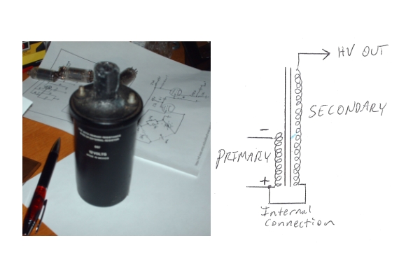
These coils come in two different kinds, and are not expensive. We're talking possibly $30 apiece. The first, and possibly most commonly recognized in these designs, is show in the photo below:
Inside the metal can is a laminated core of silicon steel, around which is wrapped a primary coil, where low voltage is applied in pulses, and a secondary coil of several thousand turns, where HV is generated. As the schematic diagram shows, this is not a true transformer in the normal sense; it is an autotransformer, where the "ground side" of the HV winding is common to the primary. As such, the only way to connect these coils so as to achieve 2x output voltage is to connect their primaries in antiparallel, so as to put the HV outputs in inverse phase. These are serious coils; 60kV potential difference is possible if driven properly.
The second kind is shown below:
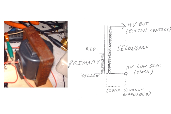
Similar to the can-type coil, except for these differences: for one thing, there is no oil within these coils, they are epoxy encapsulated, and the silicon steel core is a shell-type setup. The two welds of the shell core can be carefully sawn through if desired, and the core removed. Under normal circumstances, there's no advantage to this, but if a high-frequency driver is being used, this reduction in inductance can dramatically increase available current rise and collapse times, stepping up the voltage to even higher levels. Air also does not magnetically saturate; steel eventually will.
A second difference is the fact that this is a true transformer. The primary and secondary windings are not galvanically connected in most coils of this type. This allows a somewhat better degree of isolating the low-voltage driver circuitry from the HV output, prolonging the life of whatever active components are being used. Again, these coils can be antiparalleled for 2x output. Taking the output from these coils is somewhat trickier, as the HV terminal is usually a recessed button of metal, which under normal use would contact the rotor brush in a car's distributor. What I usually do is carefully solder a wire to this button, after sanding off whatever oxide layer may have formed on it, and then slide a 4" long 1/2" diameter plastic pipe length (PVC is a good choice here) over the wire and center it's aperture over the metal button. A thick layer of epoxy gel can be built up around the seam between coil and pipe, fastening the pipe mechanically to the coil, and providing an insulating barrier against arcover to the low voltage side.
DRIVER CIRCUIT
If you are using a neon sign transformer, oil ignition transformer, or (carefully) a microwave transformer, obtaining HV is as simple as plugging the primary winding into the wall. This can be rectified to DC by constructing a bridge rectifier of HV diodes rated for at least 1.414x the secondary AC voltage. In principle, this rating should be higher; I have found however that most HV components are significantly derated by the manufacturer, so unless you're constructing something where component failure would be extremely detrimental, don't be too concerned. HV diodes may be obtained from online suppliers, or liberated from discarded microwave ovens. On the output of the HV bridge rectifier, you could place a capacitor of suitable voltage rating (1.414xVsec or greater, again higher preferred...), but know that you are now multiplying the danger of this device significantly. Capacitors store a fair amount of energy, and at thousands of volts, are quite capable of stopping your heart should YOU become the discharge path. This danger can be alleviated somewhat by placing a limiting resistor on the final HV output from the capacitor.
To drive ignition coils, plugging them directly into the 120VAC mains is not appropriate. A source of high-rise or fall time current is needed, which can be accomplished by several means. For a very crude and simple setup an electromechanical relay can be used, but this is far from ideal and is certainly not as fast as modern semiconductors. One off-the-shelf part available as closely as the nearest hardware store is the ubiquitous "light dimmer" switch. If you've looked for this sort of thing online, no doubt you've seen the circuit shown here:
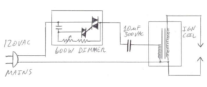
The operation of this setup, simple though it is, isn't entirely obvious from first glance, and is less than often explained. The light dimmer contains a few components, usually a TRIAC and a DIAC (both semiconductors similar to an SCR), a potentiometer, and some other stuff to suppress high frequency noise in normal applications. When connected to a load (the coil-capacitor combination) and a supply of 120VAC from the mains, what happens is the DIAC conducts at some part of the 120 volt sine wave, this point of conduction controlled by the potentiometer setting. The DIAC fires, triggering the gate of the TRIAC, which then conducts until the sine wave voltage goes to zero. This 'chopped' sine wave is then sent through a current-limiting capacitor to the primary of the ignition coil (or two, if used), and the switching current induces a very large voltage in the secondary. The waveform generated by this, as seen by the primary of the ignition coil(s) is shown in the two oscilloscope photographs below.
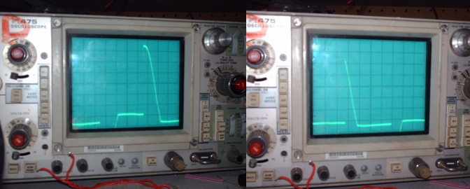
The left image is that of the dimmer control switched about 75% to maximum. A 60W light bulb driven by this would be illuminated to nearly it's full brilliance. The right image is of the dimmer control advanced further, to perhaps 30%. The bulb would be noticeably dimmer. What is interesting, however, is that when this is used to drive the ignition coil circuit, the opposite occurs. The left waveform, which gave the brightest illumination of the bulb, would give a much LOWER voltage output than the righthandside one. If at first this seems counterintuitive, recall that a normal sine wave will give no or little output from the coil. The problem is that the current does not switch fast enough to induce a significant EMF in the secondary. It is not the slowly changing part of the above waveforms which gives the greatest voltage; it is the part where the voltage (and current) is rising so fast that the oscilloscope trace seems to vanish, going straight up and down. It also appears that magnetic saturation from a too slowly changing waveform can reduce the output. As such, the waveform which has the most rapid rise and falltimes will produce the best results. A visual indication that this is the case can be seen in this picture:
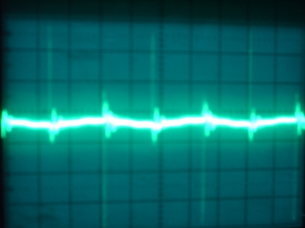
This is the waveform displayed from a long wire held a couple of feet from the ignition coil as it was sparking from the HV terminal to primary ground. The waveform is basically symmetrical, as could be expected from the identically chopped + and - peaks of the sine input. The HV pulses themselves are very brief spikes, generated almost entirely during, again, the rapidly changing part of the primary current. Some damped oscillation following the spikes of HV is also visible in the trace. A photograph of the coil setup which yielded these results in operation:
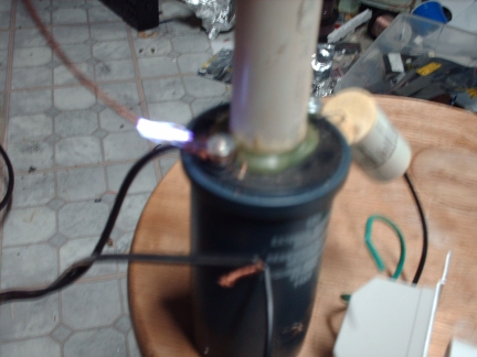
If you do this, at least insulate the 120VAC wires, as I did not myself do.
Recall that if a current is allowed to flow in a coil of wire with significant inductance, a relatively strong magnetic field is produced. This field stores energy, and if the current is suddenly interrupted, the collapse of this magnetic field deposits energy back into the coil. A much higher voltage than was initially input can be attained. That is the basic principle of ignition coil operation. Recall now the photographs of the chopped sine wave sent through the ignition coil via the TRIAC-DIAC dimmer; there is a rapid rise from zero, then a slow taper of current back to zero, and then a repetition of this in opposite polarity. Knowing all of this, would it not make sense to reverse the waves, and have instead a slow rise to establish a strong magnetic field, and then a rapid collapse?
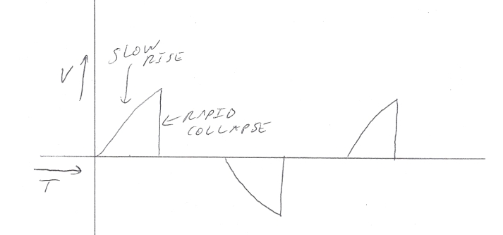
To do so, we would need a more complex circuit, mains synchronized. I have not to date done this, as I tend to utilize other power supplies for my own research, but it is something interesting to think about, and a possible future project. A TRIAC-DIAC circuit would not work; these are normally off devices, which are turned on by a gate impulse. We would need something which always conducts until turned off. A MOSFET (use a depletion mode type, perhaps?) might do quite well if driven appropriately and protected from back EMF. I have not seen any MOSFET circuits which do this on the internet, but they may well exist. It should not be too complex a thing to design.
This Web Page Created with PageBreeze Free HTML Editor